Introduction
This writing describes a method for measuring the noise spectrum of voltage regulators. As a bonus, one can also measure the thermal noise power of resistors with the same measurement set-up.
For oscillators on microwaves, a low-noise power supply is of great importance. Among other things, PLL boards for sale on Ebay often do not always contain low-noise voltage regulators that make the use of these boards without modification undesirable.
Measuring the noise of voltage regulators is not difficult, but building a good measurement set-up does take some effort.
Note: click on the images on this page to enlarge them
The measurement set-up
The measurements are based on publications by Thomas Baier DG8SAQ in FunkAmateur (1). His publication has prompted many others to repeat and further elaborate the experiments described there. A number of important sources are listed in the bibliography at the end of this article.The measurement set-up consists of a computer with the AudioMeter software package developed by DG8SAQ. In order to have sufficient dynamic range and also sufficient measuring bandwidth, a good external sound card is recommended. A low-noise amplifier (LNA) feeds the sound card to enable the measurement of very weak signals.
The Device Under Test (DUT) measurement takes place in a shielded room to avoid measuring nuisance radiation from nearby devices, especially 50 Hz emissions.
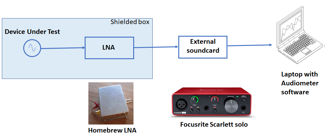
figure 1 System set-up
The computer
The computer is not critical, almost any Windows computer can be used, but a laptop is recommended as it can be used without AC power to avoid 50 Hz interference during sensitive measurements. The AudioMeter software can be downloaded from the DARC website (4). The AudioMeter software is user-friendly, but the package contains options that you will not immediately find. Reading the original DG8SAQ article is therefore recommended.
The external soundcard
A sound card with a good frequency response, a large dynamic range and a high sample rate is recommended. On the advice of Harke, PA0HRK, I used the Focusrite Scarlett solo; 24-bit range and 192 kHz sample rate. Theoretically this allows a dynamic range of 144 dB and a bandwidth of 96 kHz. In practice, more than 110 dB of measurement space and a bandwidth of approximately 60 kHz is available.
The LNA
The ideas for the LNA come from a publication by Charles Wenzel (3). Two JFETs in parallel and an LM833 first stage give a DC-coupled gain of 30 dB. This is followed by a second stage also with an LM833 and also with 30 dB amplification. So the total gain is 60 dB or 1000 times. 2 Li-ion ‘9 volt type’ batteries with a voltage of approximately 7.5 volts power the LNA.
Two 2SK369BK FETs connected in parallel (selected for equality and high IDSS) achieve a remarkably low noise voltage. It is important to use high quality components in the LNA, such as metal film resistors and low ESR electrolytic capacitors. A jumper circuit on the input of the LNA offers the possibility to short-circuit or terminate the amplifier with a resistor of 50 Ohms. To keep interference fields out of the amplifier, it is housed in a metal box; for me it just fits in a standard tin box of 74 x 55 x 30 mm. See also the photo of the LNA. To prevent ground currents and interference as much as possible, the housing is only connected to the amplifier ground in one place.
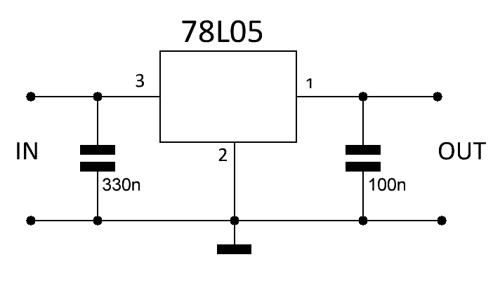
The scheme I used is below. More ideas, descriptions and settings can be found on the bibliography pages at the end of this article, e.g. in (2).
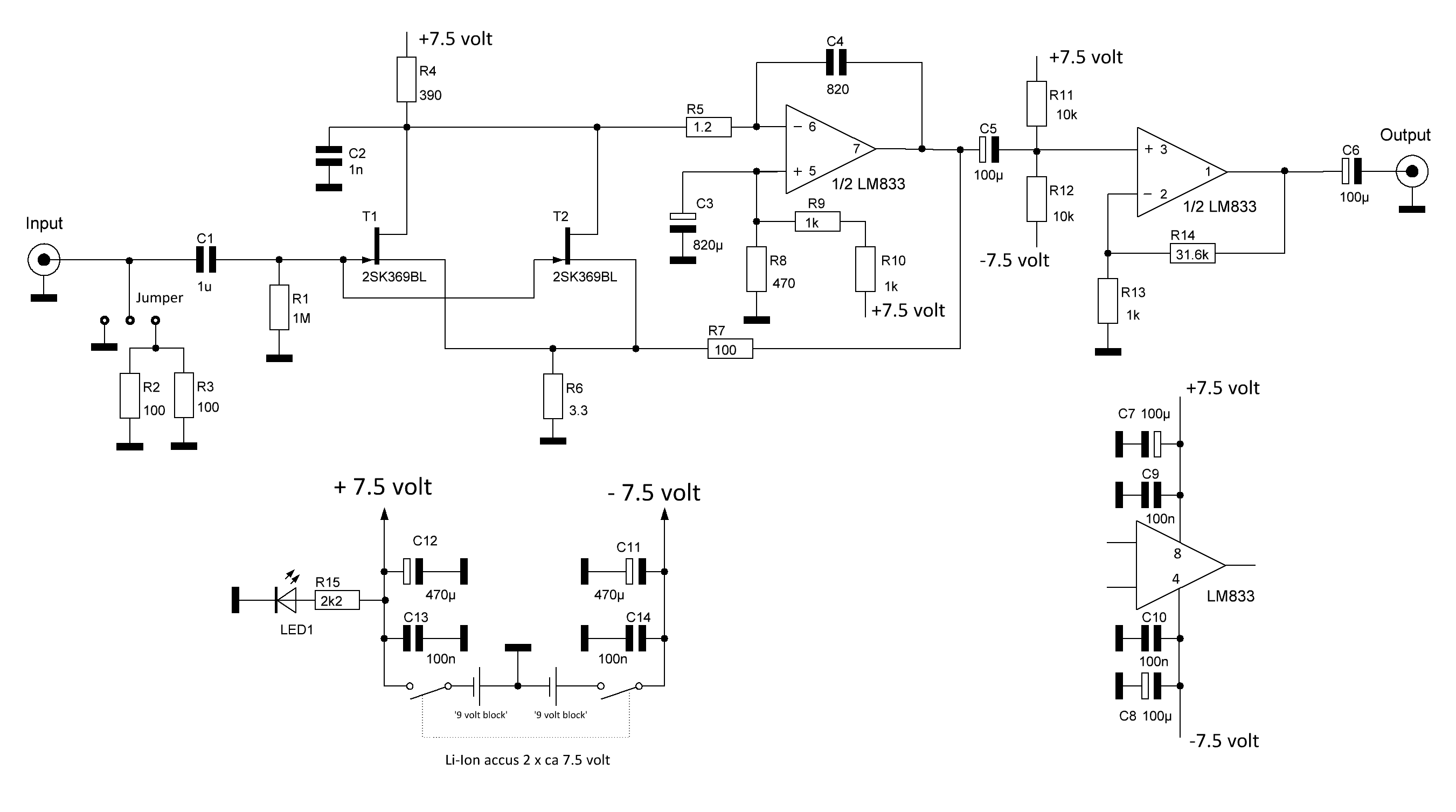
Figure 2 Schematic of LNA
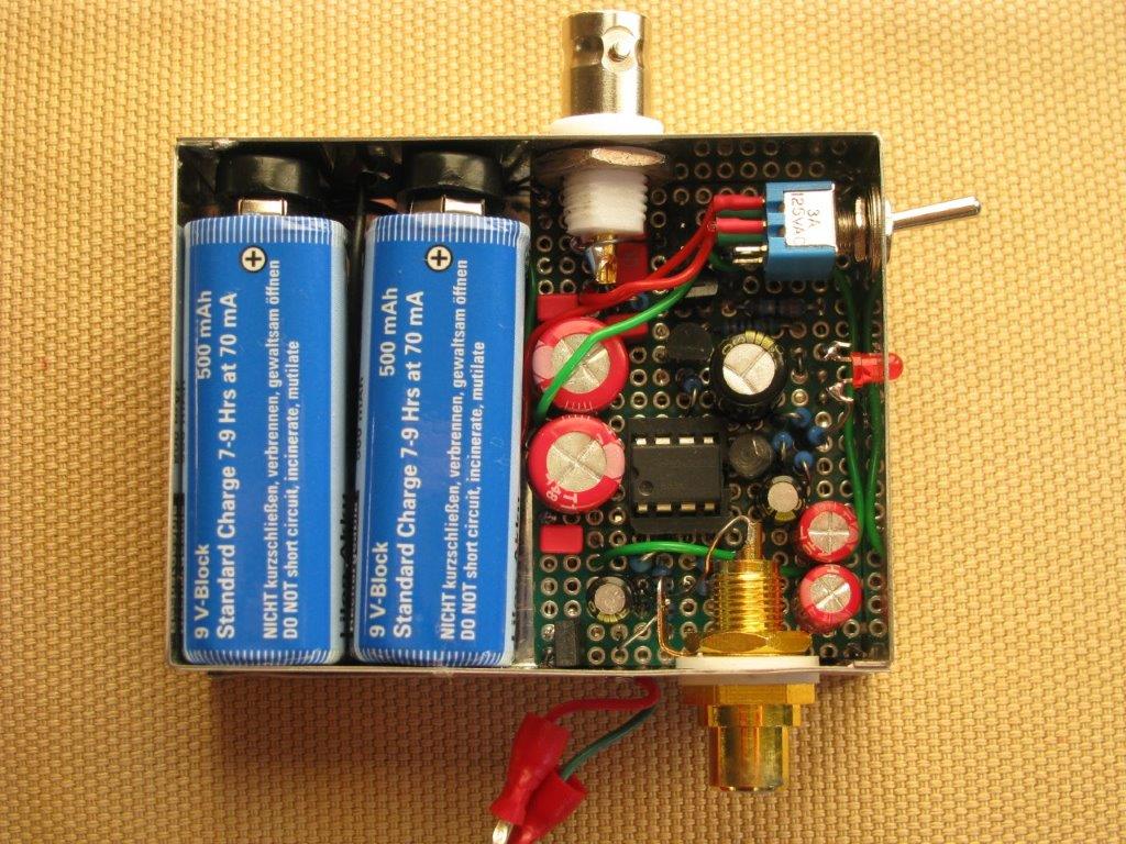
Figure 3 Photo of LNA
The ‘Faraday’ cage
The measurements are very sensitive. Interference from various sources such as the mains, LED lamps, USB cables, etc. can be avoided by placing the measuring object (DUT) and the preamplifier in a metal box. A large cookie jar is perfect for this.
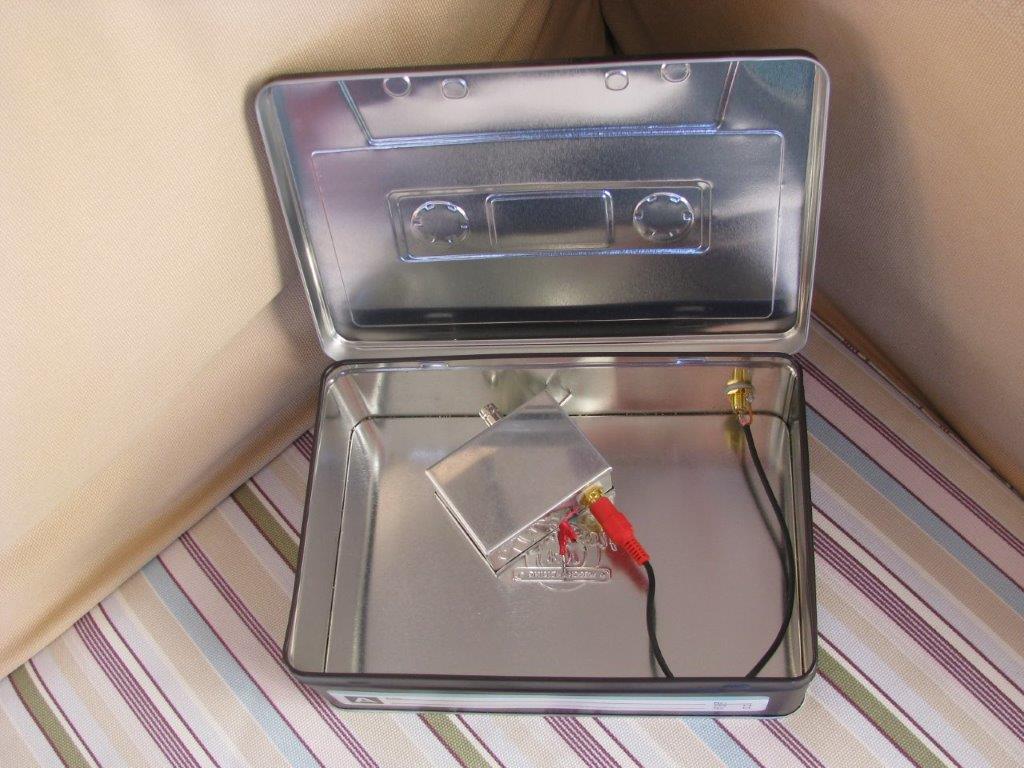
Figure 4 A cookie tin used as a Farady cage
Calibration
The calibration is done by applying an input signal of known amplitude to the external sound card. It is recommended to do this for a number of frequencies within the measurement bandwidth. From the AudioMeter documentation: Enter the peak-to-peak voltage value into the input field on the “Measurement” tab. Press the SetRefLevel button. Done! To check the whole chain (sound card and LNA), a calibrated 60dB attenuator is useful; because the LNA amplifies a signal 1000 times = 60 dB.
Measurements
The measurements are done in a 50 kHz range: 20 Hz to 50020 Hz.
The baseline
As the system is calibrated with a known value, a first measurement can be carried out by measuring the sensitivity of the short-circuited external soundcard. The results are in the picture: S+N = 60.8 𝑢𝑉rms and a spectral density of 272 n𝑉rms/√Hz. This is not a very good value, but (no panic) an LNA will be added to the circuit.
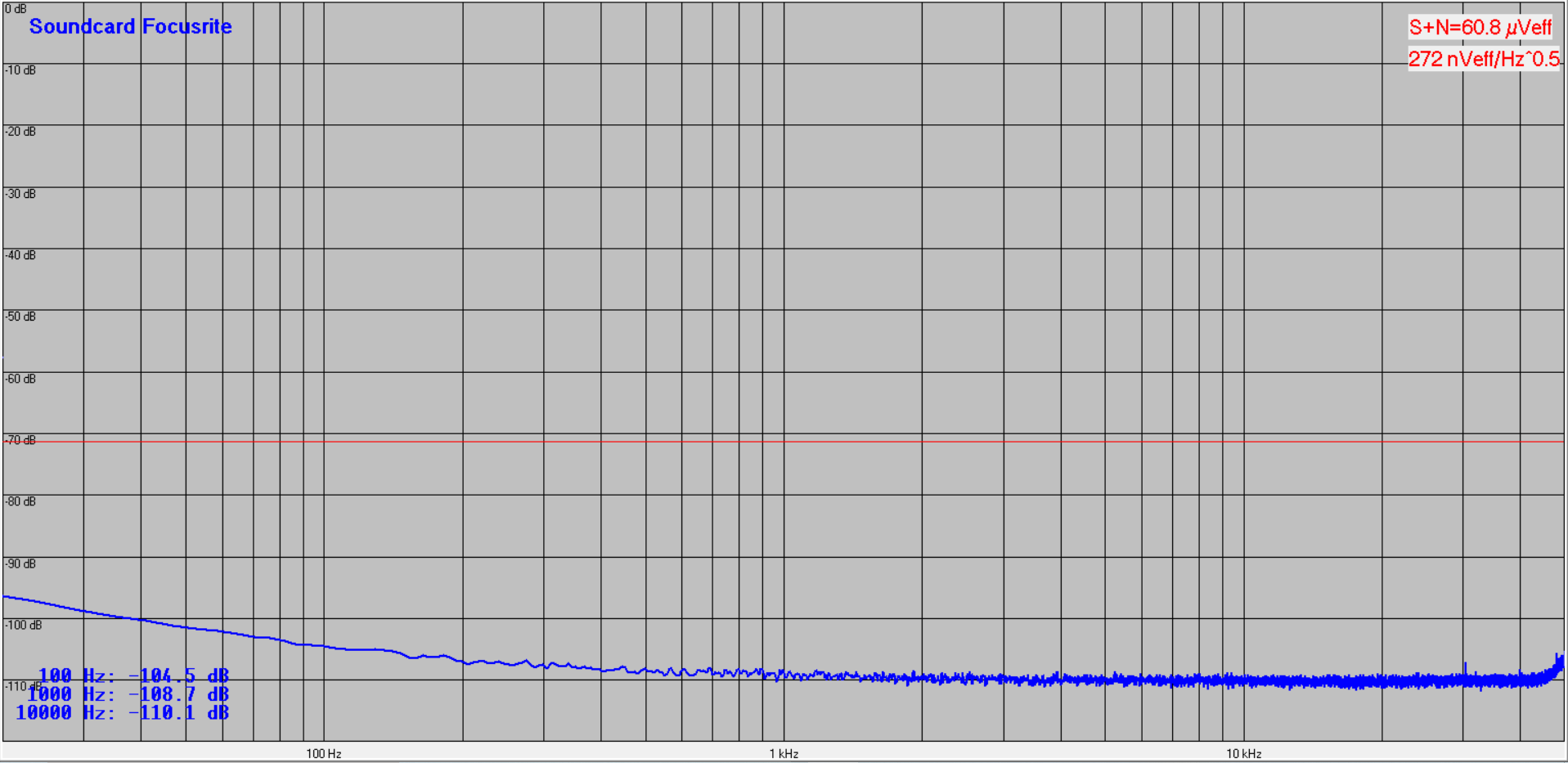
Figure 5 Sensitivity figures of the soundcard
The LNA will be added at the input of the soundcard and measured. Keep in mind that the amplification of the LNA is 1000 times. Although the LNA amplifies 1000 x the noise of the system increases to a limited extent because of its excellent noise properties. In the diagram you can see that the short-circuited LNA measures an S+N = 126 𝑢𝑉rms and a spectral density of 567 nVrms/√Hz. As the LNA amplifies 1000 x the total system has a spectral density sensitivity of 0.567 nVrms/√Hz. The noise floor for the measuring system is determined by this. The 0.567 nVrms/√Hz is a good value, but improvement is possible as the noise of the soundcard is only 6 dB less. A margin of at least 10 dB is needed to neglect the soundcard noise. Adding extra gain to the LNA is the straightforward solution. This is probably an improvement for the near future.
Note: S+N = spectral density (Vrms/√Hz) x √(bandwidth (Hz)) = S + N = 567 nVrms/√Hz x √ 50000 Hz = 126 𝑢𝑉rms.

Figure 6 The sensitivity of the measuring system
Measuring thermal noise of resistors
Electrons constantly move In all conductors. As temperature increases, the movements increase. The vibrations of the electrons cause a constantly changing electric signal across the thermals of the component. Because the vibrations are completely random, the electrical signal is noise. This is called thermal noise or Johnson noise. Thermal noise is produced by all resistors regardless of type. Thermal noise is constant over a wide frequency range.
Measuring the thermal noise power of resistors is quite easy with the described system set-up. Mount the resistor at the input of the LNA and read the measured noise voltage in the graph. Possibly corrected for the LNA noise at low resistor values.
The Power Spectral Density describes how much noise power would generated by a resistor per Hertz of bandwidth.
S = 4 k T R (V2/Hz)
k the constant of Boltzmann 1,3806 x 10 -23 Joule per degree Kelvin
T the temperature in Kelvin
R the resistor value in Ohm
V = √4 k T R (Vrms/√Hz)
Calculations and measurements
Shack temperature: 20 degree Celsius = 273 + 20 = 293 degree Kelvin.
| Resistor value (Ohm) | Calculated (nVrms/√Hz) | Measured (nVrms/√Hz) |
| 50 | 0.90 | 1.05 |
| 1000 | 4.02 | 4.04 |
| 10000 | 12.7 | 12.6 |
For the 1000 en 10000 Ohm resistor the measured and the calculated values are quite the same; temperature, resistor tolerance and measuring system accuracy declare the small differences. For 50 Ohm we have to take into account the system noise floor: √ ( 0,902 + 0.572) = 1.07 nVrms/√Hz. This is in line with the measured value.
Wikipedia: A useful rule of thumb to remember is that 50 Ω at 1 Hz bandwidth correspond to 1 nV noise (voltage) at room temperature.
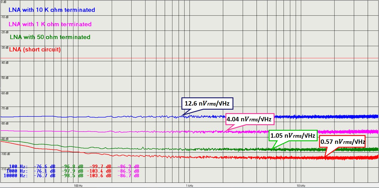
Figure 7 The measured thermal noise of resistors
Noise measurements on voltage regulators
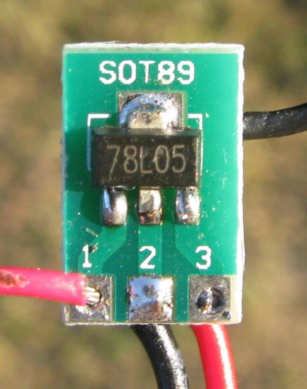
The first DUT was an 78L05. This voltage regulator is used frequently and is ‘famous’ for its impressive noise spectrum.
The measured noise spectrum of the device which supplies a current of 40 ma is in the figure below.

Figure 8 Noise spectrum of an 78L05 compared with the noise of the LNA
The measured spectral density of the 78L05 is 241 𝑢𝑉rms/1000 = 241 n𝑉rms; the LNA baseline is 0.57 nVrms/√Hz. The difference in dBs is: 20 log (241 n𝑉rms/0.57 n𝑉rms) = 53 dB. This value can be read in figure 8.
Several voltage regulators of this type were measured like LM317, 7809, etc. The results were in the same range.
For use in (microwave) VCO’s and PLL circuits ultra-low noise regulators are recommended. Two types are measured: the LT3045 and the ADM 7150; both supplying 40 ma.
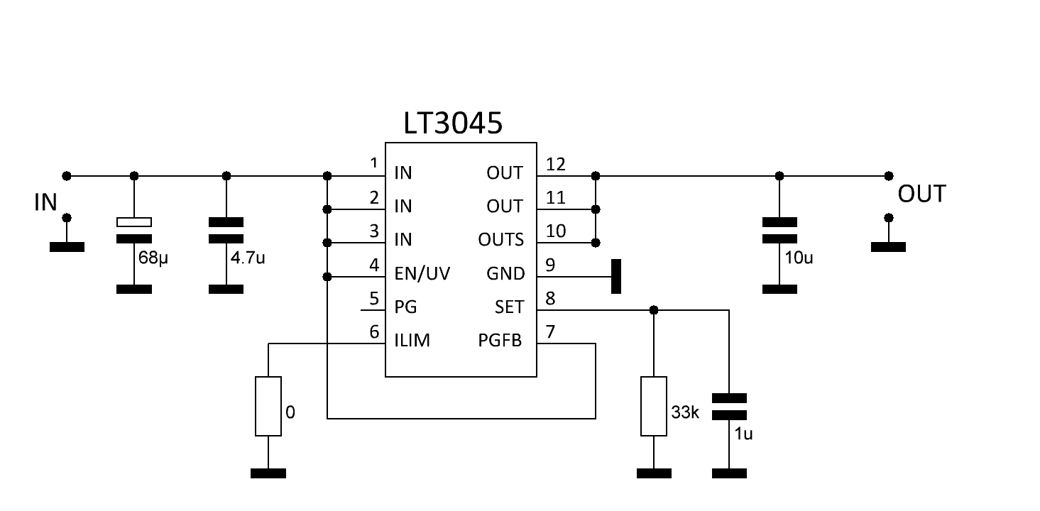
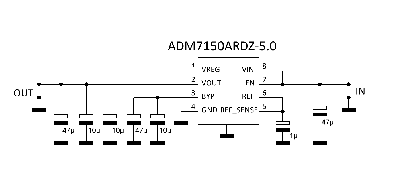
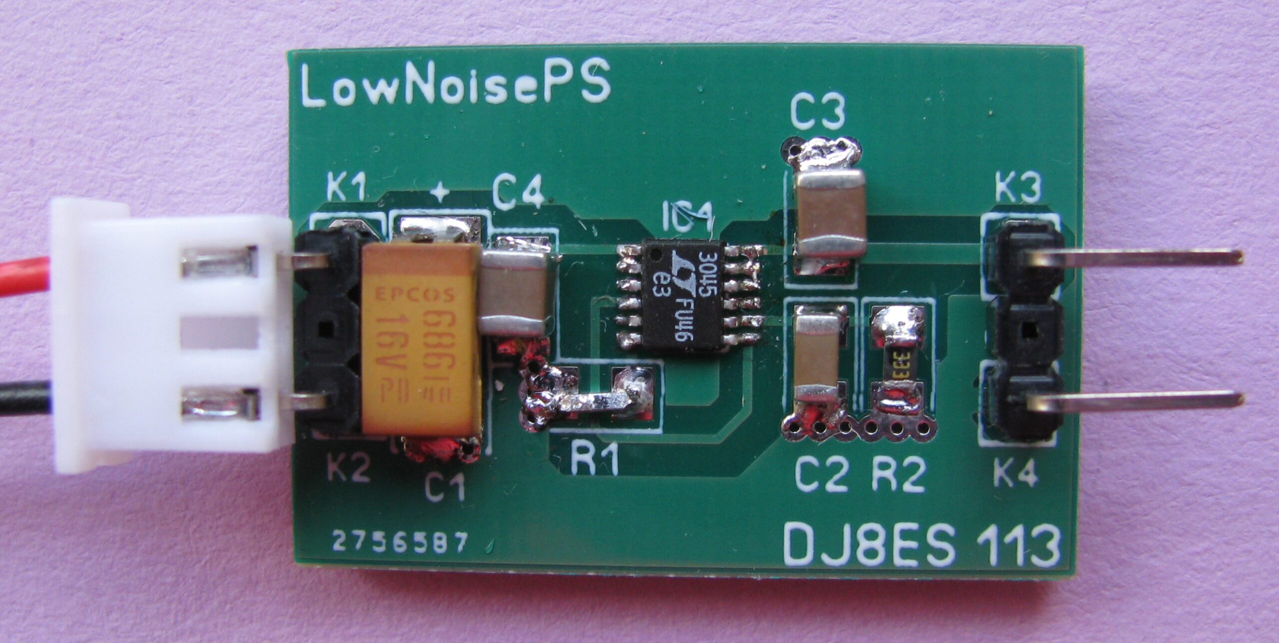
Figure 9 LT3045 on a board designed by DJ8ES
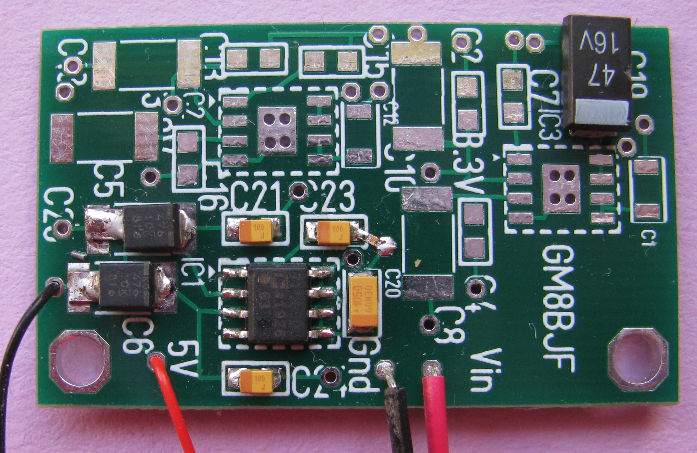
Figure 10 ADM7150 board of GM8BJF
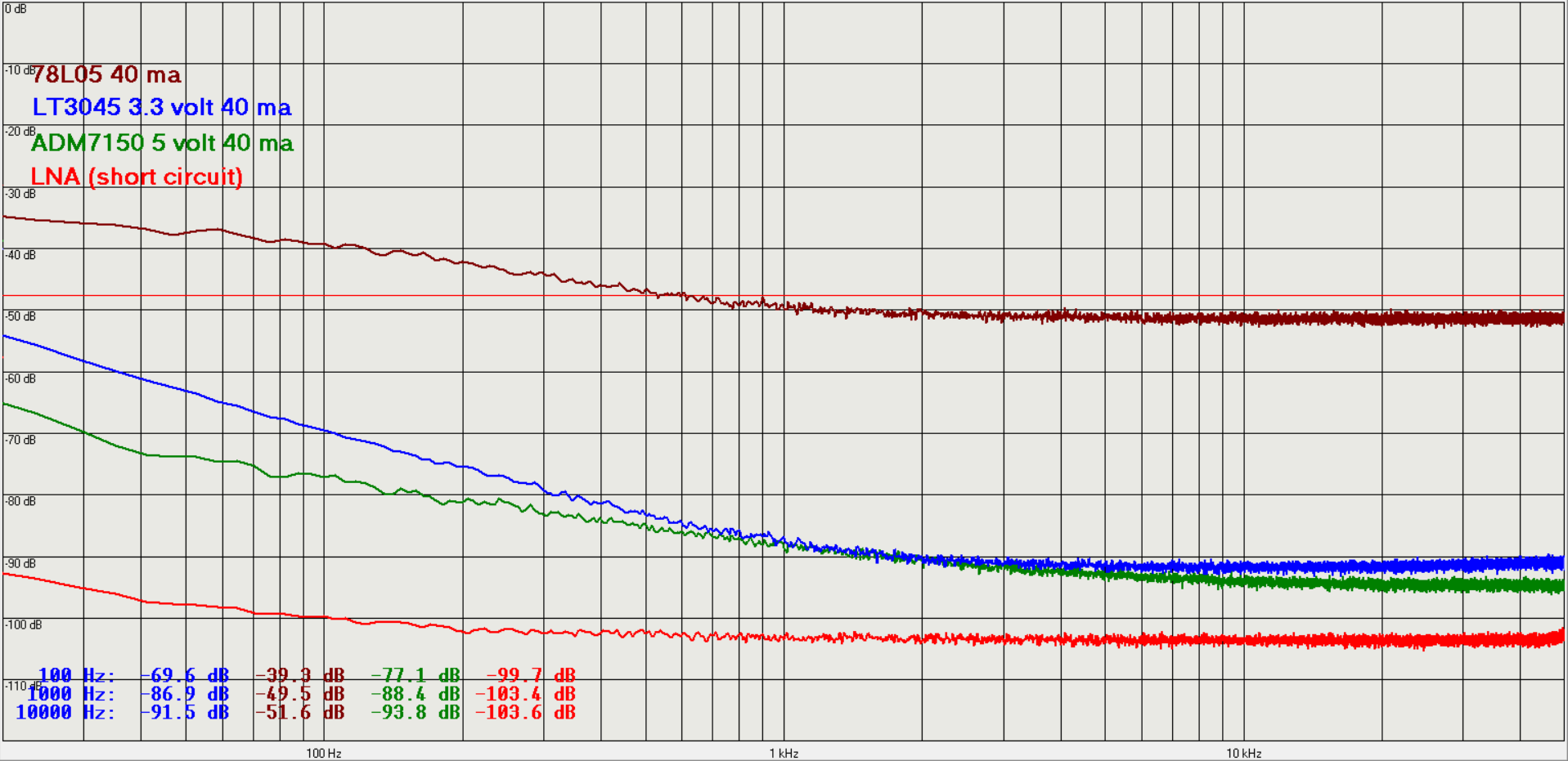
Figure 11 Noise spectrum plotted for 78L05, LT3045 and ADM7150
From the measured graphs it is clear that both the LT3045 and the ADM7150 are really low noise types.
Calculation: The datasheet of the ADM7150 specifies the noise spectral density as 1.7 nV/√Hz from 10 kHz to 1 MHz. In figure 11 we can read at 10 kHz for the LNA -103.6 dB and for the ADM 7150 -93.8 dB. The LNA has a noise spectral density as 0.57 nV/√Hz; this means the measured noise spectral density of the ADM7150 is 1.76 nV/√Hz. So we can trust the datasheet….
At a first glance the LT3045 measured values are also comparable with the specifications. Both regulators the ADM7150 and LT3045 have excellent low noise performance. The ADM7150 is only available for fixed output voltages; the LT3045 can be tuned between 0 and 15 volt output.
The noise spectrum can be influenced by adding an extra low ESR 1000 μF elco at the output of a voltage regulator. For the LT3045 the application note writes: “hence, there is little to be gained by using larger than the minimum 10 μF output capacitor. Nonetheless, larger values of output capacitance do decrease peak output deviations during a load transient “ The result is plotted in figure 12. After reading the application note, the profit is greater than expected.
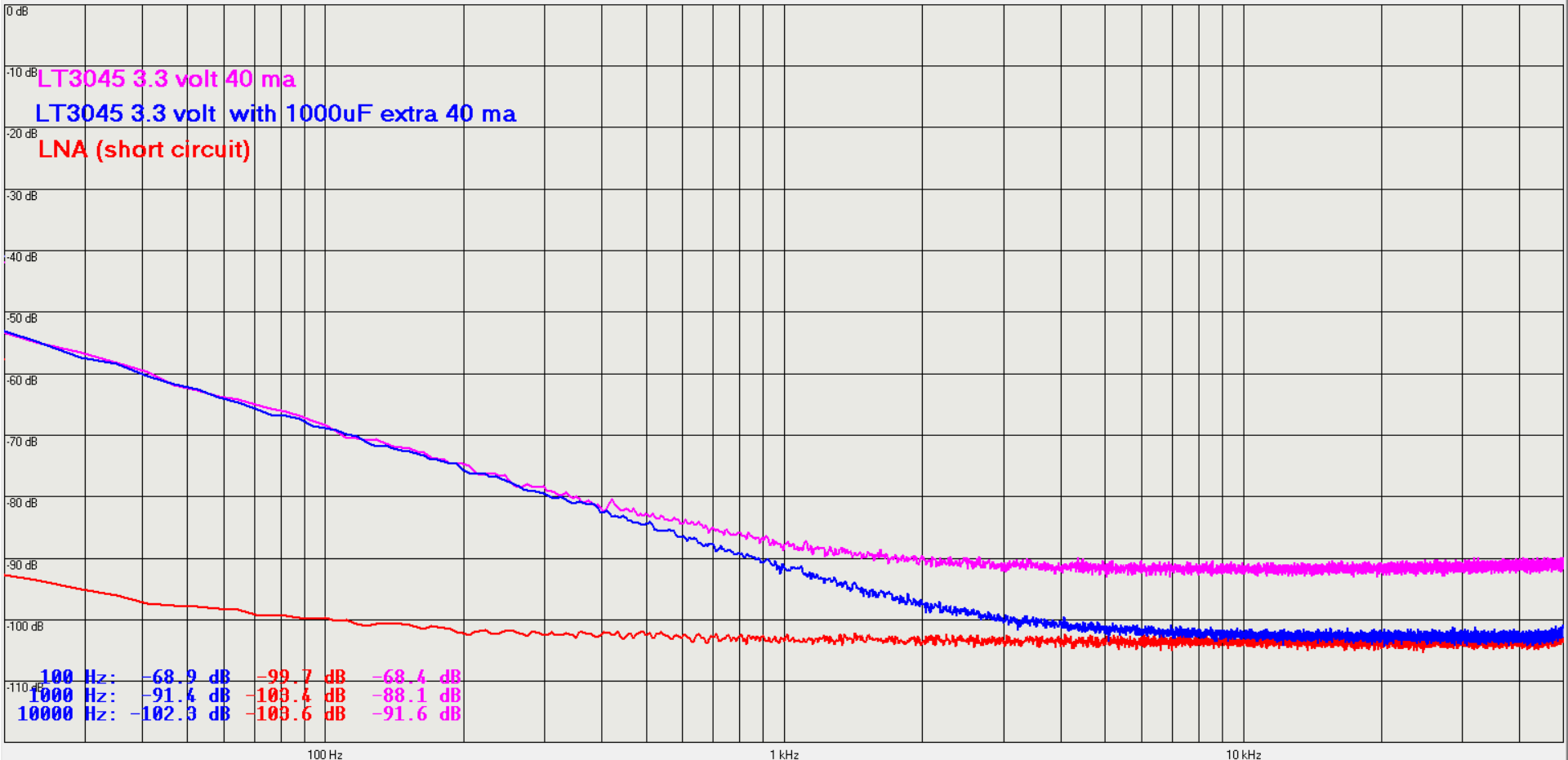
Figure 12 Noise spectrum LT3045 with extra low ESR 1000 μF elco at the output
Measurements on the LT1761-3.3.
The LT1761 is a 100 mA low noise, low dropout regulator. From the datasheet: “With an external 0.01μF bypass capacitor, output noise drops to 20 μVrms over a 10Hz to 100kHz bandwidth.”
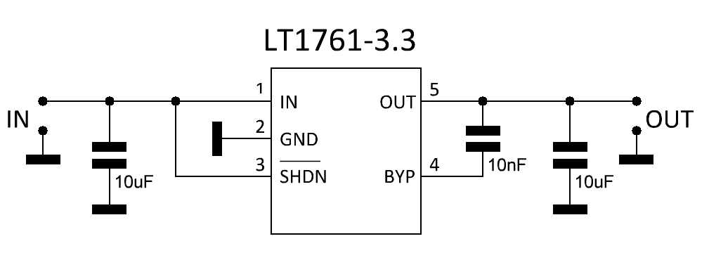
Figure 13 The LT1761 schematic
Measurements on the LT1761-3.3 (see components values in Figure 13) supplying 40 mA output current are in the next figure. An extra test has been made with an additional low ESR 1000 uF capacitor at the output port.
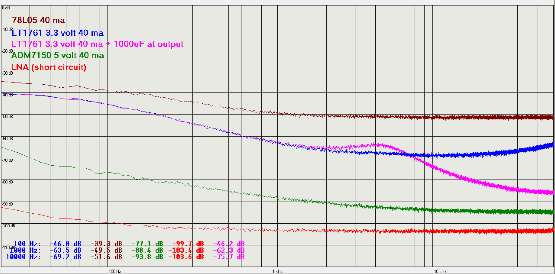
Figure 14 Measurements on the LT1761
In his article (5) Harke, PA0HRK, pointed out that it is obvious that an RC network at the output of a voltage regulator reduces the noise spectrum. This is a simple addition that can be very useful in some cases. I did some experiments for the LT3045 with an RC network of 1 Ohm/1000 uF, 10 Ohm/1000 uF and (for fun) 1 Ohm/1.5F. The results are in the figure below. Depending on the application (with some voltage drop), this is a nice solution. Using low ESR elcos is recommended.
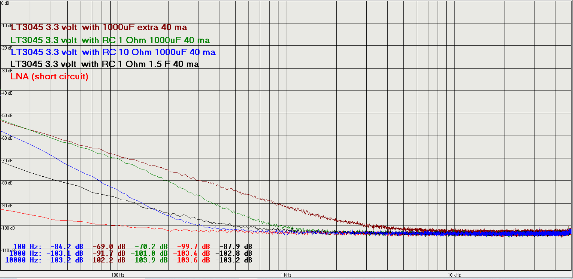
Figure 15 Noise spectrum influenced by an RC network at the output
Note: For certain applications it may be useful to also consider other voltage regulator noise reduction circuits, e.g. as described in (6) and (7).
Using other soundcards
For many measurements there is no need for a dynamic range of 24 bits. A test with the internal soundcard of an ACER swift 3 with 14 bits and a sample frequency of 48 kHz was carried out. The results are shown in figure 16.

Figure 16 Noise measurements carried out with the internal soundcard of an Acer Swift 3
Also some measurements with an external USB soundcard (see photo) were done. The results were really nice: see figure 18.
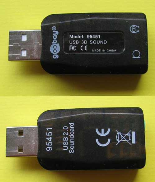
Figure 17 photo of the used USB soundcard
Note: Some USB soundcards which look quite similar to the one shown in the photo clearly delivered worse results.
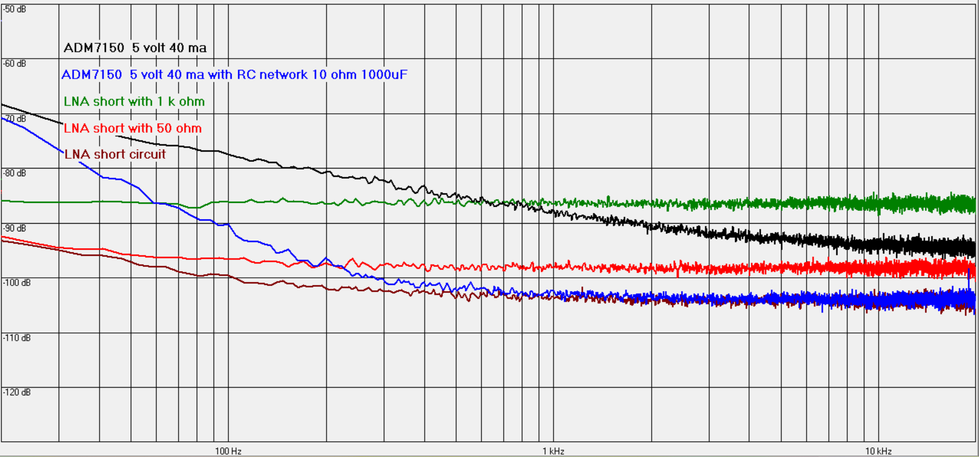
Figure 18 Measurements carried out with an external USB soundcard
Final words
The low-noise voltage regulators ADM7150 and LT3045 are well suited for powering microwave PLL and VCO circuits. A very low noise level can be achieved by adding some additional components.
The combination of Audiometer, sound card and an LNA is very suitable for building a (phase) noise measurement system.
When high dynamic range is not required and limited bandwidth is sufficient, the internal sound card of a laptop or a simple external USB sound card can be used.
Measuring the thermal noise power of resistors was very interesting and was a real eye opener because I previously thought that was not possible with simple amateur equipment.
Literature
Referenced articles
- Audiometer Software zum Messen mit der Soundkarte Thomas Baier DG8SAQ FunkAmateur 10/2014 and 11/2014
- Sehr rauscharmer 60 dB Verstaerker bis 500 kHz linear Bernd Kaa DG4RBF FunkAmateur 10/2015
- A Low Noise Amplifier for Phase Noise Measurements, Charles Wenzel: http://techlib.com/files/lowamp.pdf
- https://dg8saq.darc.de/AudioMeter/index.shtml
- Ruisspectra van DC voedingen, Harke Smits, PA0HRK
- Finesse voltage regulator noise, http://www.wenzel.com/documents/finesse.html
- Simple circuits reduce regulator noise floor, https://www.edn.com/simple-circuits-reduce-regulator-noise-floor/
Recommended articles
- Der Einsatz von Soundkarten zum Empfang von VLF-Signalen und als Messgerät: http://www.g-qrp-dl.de/Projekte/Soundkarte/Einsatz%20von%20Soundkarten.pdf
- pdf, Jörn Bartels, DK7JB, https://www.bartelsos.de/messtechnik/untersuchungen-an-baugruppen/rauschen-spannungsregler
- Rauschmessung an modernen rauscharmen Spannungsreglern, Bernd Kaa, DG4RBF, UKW-Berichte 3/2021