Programming ADF Frequency Synthesizers
General
The settings of the ADF synthesizers (phase detector frequency, output frequency, current, etc.) are determined by the contents of a number of registers in the ADF.
The contents of these registers for the ADF can be calculated using Analog Devices software. This software is published on the Analog Devices (Engineering) pages. For example, the ADF 4002: search for ADI PLL Int-N software, for the ADF4351 search for EVAL-ADF4351 or ADF435x, for the ADF5355 search for EVAL ADF5355.
With an Arduino, programming an ADF is easy. In order not to have to use level shifters, a 3.3-volt Arduino is recommended. An Arduino with a USB interface makes it easy to connect to the computer.
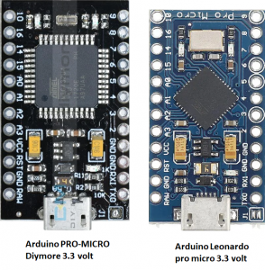
Here are 2 examples:
1) Arduino Leonardo pro micro 3.3 volts
2) PRO-MICRO 3.3volt from Diymore
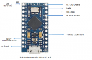
The schematic is straight forward. Data, LE and CLK are used to populate the registers of the ADF. With CE (= Chip Enable) the ADF is unlocked. The CE connection of the ADF may also be connected continuously to the 3.3-volt line.
Added to the schematic is an LED that lights up during data transfer to the ADF. The push switch allows the Arduino to be reset.
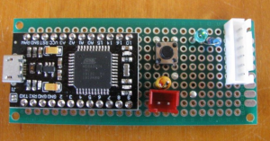
Practical realisation
ADF5355
The ADF5355 has 13 registers of 32 bits. The registers are filled one by one with register 12 first and then register 11 and so on up to register 0. To fill these registers, the 32 bits of data (Data line) are clocked into the 32-bit shift register of the ADF on each rising edge of clock (CLK). The data clocks in MSB first. Data transfer from the shift register to one of the 13 latches occurs on the rising edge of LE (Load Enable).
Arduino software for programming an ADF5355 (reference frequency 26 MHz Fout=400 MHz)
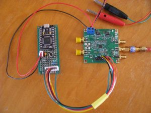
ADF5355 board connected to Arduino